

[Repair Case] 2019 Audi uses a 3D printer to make an Audi e-tron gearbox installation
Posted by Tony Brown on
Model: e-tron
System: Transmission
Year: 2019
Driving mileage: 9,383 miles
Issue: The driver's guide in the instrument cluster displays "Coolant level too low" and the coolant indicator light illuminates in red.
Troubleshooting:
First check that the coolant level in the expansion kettle is below the lower limit mark. Connect the diagnostic instrument to read the fault code, there is a fault code in the temperature management system control unit J1024 (address code C5): the coolant is insufficient, and the low liquid level of the sensor is displayed.
Next troubleshooting for the coolant leak revealed excess coolant inside the front motor. According to the Volkswagen technical standards, bolt 1 is a maintenance inspection bolt (as shown in Figure 1), and the technical standard leakage is 32mL/30000km; bolts 2 and 3 are drain bolts, and there should be no excess coolant inside. The actual test result is that the total amount of coolant leakage of the front motor is about 800mL, and the front motor assembly must be replaced according to the maintenance standard.

Figure 1
Check the information and replace the front motor. The specific implementation process is as follows:
First cut off the power to the high voltage electrical system and remove the front motor/gearbox together with the front subframe. Lift the motor and gearbox to separate them from the subframe. The next job is to disengage the front motor from the gearbox.
Audi e-tron models use a single-speed gearbox. Unlike conventional transmissions, after the motor is separated from the gearbox, the gearbox on the side facing the motor is open. At this time, the oil guide, planetary gear set, bearings and other mechanical parts are all exposed. Therefore, after removing the gearbox, more attention must be paid to the cleanliness of the environment. While paying attention to the maintenance tips, the maintenance technicians strictly followed the instructions of Volkswagen Elsa one by one: drain the gearbox oil, remove the front motor accessories, remove the flange shafts on both sides; loosen the connecting bolts between the front motor and the gearbox; use special Lift the front motor with the tool (as shown in Figure 2), and ensure that the gearbox is close to the work surface when removing the connecting bolts and separate the front motor.
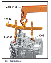
Figure 2
At this point, the disassembly of the front motor is completed. The next step is to complete the changes to the new motor and complete the assembly. According to Elsa standards, after replacing the front motor, the necessary measures are:
1. Remove the left flange shaft oil seal of the gearbox (as shown in Figure 3) and install a new right flange shaft oil seal (as shown in Figure 4).
2. Install a new roller bearing (as shown in Figure 5 and Figure 6).
3. Check the positioning pins (2 pieces) (as shown in Figure 7).
4. Determine the adjusting shim of the thrust bearing (as shown in Figure 8).
5. Determine the adjusting shim of the angular contact bearing (as shown in Figure 9).
6. Install the new front motor differential oil seal (as shown in Figure 10).
7. Install other related accessories (which also include the missing parts of the new motor after comparing with the old motor, or the parts that need to be replaced after being removed from the old motor).

Figure 3

Figure 4

Figure 5

Figure 6

Figure 7

Figure 8

Figure 9
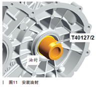
Figure 10
After the above work is completed, the assembly of the new motor and gearbox can be carried out. During the assembly process, the service technician ran into trouble - the differential oil seal installed on the motor, due to its double-sided lip is elastic (as shown in Figure 11, the left flange shaft and angular contact are not shown), it cannot be assembled according to Elsa's assembly instructions.

Figure 11
According to the Elsa standard procedure, first place the gear box with the open side facing up, apply sealant after assembling the relevant parts, then lift the front motor with a crane (as shown in Figure 12), and push the gear box vertically downward. Complete the assembly.

Figure 12
During the actual operation, when the motor slowly descends, the left flange shaft and the differential oil seal need to be precisely aligned with the sun gear 2 of the planetary gear differential in the gearbox at the same time. Without the help of other suitable tools, the lip of the differential oil seal will always be pushed to the other direction by the end face of the differential sun gear 2 (the oil seal lip is twisted and turned over), even if it is installed multiple times. The inner diameter of the differential oil seal and the end face diameter of the differential sun gear 2 were roughly measured with a vernier caliper, and it was found that the inner diameter of the oil seal was slightly smaller than the end face diameter (as shown in Figure 13 and Figure 14), and the installation was relatively difficult.

Figure 13
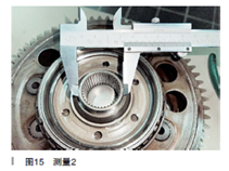
Figure 14
It can be seen from the cross-sectional view that the oil seal lip of the left flange shaft is pointing in the same direction as the motor moves in the same direction as the motor during installation. In this case, without suitable auxiliary tools or special tools, it is difficult to complete the correct installation, and will directly cause damage to the oil seal.
Following Elsa's instructions, after many failures, the service technician decided to remove the left flange shaft first. In this way, the installation of the oil seal can be observed through the installation hole of the left flange shaft; at the same time, screw the 3 guide bolts into the thread of the gearbox to match the exact alignment of the motor installation hole; finally, when the oil seal touches the When the end face of the differential sun gear 2, use a thin feeler gauge to gently press the oil seal lip that is about to be flanged until the motor is completely seated (as shown in Figure 15, the state of the oil seal after installation).

Figure 15
The next assembly work feels relatively smooth. After completing the high-voltage power recovery and power-on procedure, the test drive is carried out. But when the vehicle was in reverse gear and the brake pedal was released, the test driver found that the vehicle did not creep backwards but stood still. After tapping the accelerator, the vehicle traveled backwards at a low speed, releasing the accelerator pedal, the vehicle braked significantly and stopped in place. The same goes for forward gear. And in the process of wheel rotation, a slight metal friction sound can be heard from the vehicle chassis.
The test staff and maintenance technicians carefully reviewed the maintenance process and confirmed that there were no omissions in the Elsa's operation steps, no foreign objects were left in the motor or gearbox, and the oil had been filled according to the standard. It was then suspected that there was a problem inside the new front motor. But just as the vehicle slowly moved to the lift frame, the front chassis made a crisp metal knock, accompanied by a "nodding" at the front of the vehicle (similar to the automatic transmission vehicle shifting into the P gear before it stopped), the vehicle stopped in place. At this point, no matter if you tap the accelerator pedal or push it, you cannot move the vehicle.
Only by dismantling and inspecting again, it is basically determined that the failure at this time is a mechanical problem.
The maintenance technician drained the gearbox oil, there is no burnt smell, the color is normal, but there are large and small metal chips. In this way, only re-disassemble the front motor and gearbox to find out.
After decomposition, several metal particles can be observed in the gearbox, and the fault point is basically locked inside the gearbox. Take out the right flange shaft. This step is also to take out the planetary light structure differential from the gearbox. So far, the Elsa system has only given the operation steps for disassembling the right flange shaft but has not given further disassembly and precautions of the gearbox.
Gearbox inspection and damage cause analysis:
Audi e-tron's 0MA single-speed gearbox has a dual-stage reduction ratio and the latest planetary gear type light structure differential. In addition, it is equipped with an electromechanical parking lock. The torque conversion is divided into two stages: the first reduction stage uses a simple planetary gear pair from the sun gear shaft (driven by the front motor) to the planetary gears and planetary gear carrier, and the second reduction stage uses a cylindrical gear mechanism to transfer torque from the planet carrier goes to the differential.
Take out the planetary gear type light structure differential for inspection, there is no abnormal wear visually, and the internal gear rotates normally. However, the simple planetary gear pair at the input end is difficult to take out. With the help of tools and external force, it can be taken out in a rotating manner. Unexpectedly, there was severe damage inside the gearbox housing (see Figure 16).

Figure 16
Looking at the simple planetary gear pair on the input side, several planetary gears have also been broken and damaged to varying degrees.
Carefully observe the damaged and scattered parts in the gearbox housing. It should be the thrust bearing. The upper and lower thrust plates have been broken, the cage in the middle is severely deformed, and a small number of balls are missing (as shown in Figure 17).

Figure 17
From the sectional view of the simple planetary gear pair at the input end (as shown in Figure 18), has a thrust bearing on both sides of the gearbox and the front motor respectively. The difference is that they belong to the same kind of spare parts.

Figure 18
The damaged thrust bearing is used between the planet carrier on the input side and the gearbox housing. It is not difficult to observe the indentation on the housing. There are obvious depressions in the indentation after being squeezed by the bearing rollers (as shown in Figure 19). That is, when the screws of the front motor and the gearbox are tightened, the pressing force makes the bearing rollers squeeze into the gearbox housing.

Figure 19
Compared with the intact thrust bearing on the other side, the upper and lower thrust plates cannot be separated, and the bearing rollers are even less likely to slip out between the two thrust plates during assembly.
So, how are the upper and lower thrust plates separated? Preliminary analysis: It is possible that when assembling the front motor and gearbox, the differential sun gear 2 will always squeeze the differential oil seal, resulting in too many assembly times. Because the installation was not in place and the motor and gearbox were separated several times, the simple planetary gear pair on the input side accidentally slipped out a short distance, and the thrust bearing on the housing side of the gearbox slipped out. In the following repeated assembly, the thrust bearing was damaged without returning to the seat, and the inner roller of the thrust bearing was separated from its thrust plate. The occurrence of this situation may cause the simple planetary gear pair to be slightly higher than the original position, but because the tooth surface heights of the input spur gear 1 and the output spur gear 2 of the gearbox are originally different (as shown in Figure 20 and Figure 21), the change in height difference between the two cannot be seen seen. The error occurred inside the machine, beyond the eyes of the maintenance technician. During the next test run, the falling bearing rollers got stuck in the planetary gears, resulting in a mechanical jamming accident of the gearbox.

Figure 20

Figure 21
Analyze the reasons:
For the first time, Audi has adopted the planetary gear type light structure differential produced by SCHAEFFLER (Schaeffler Group) in the e-tron model. For this kind of mechanical transmission, there are no detailed maintenance instructions and operation instructions in the Volkswagen Elsa, and the information that can be consulted is not enough to cover the entire maintenance process.
Throughout the entire maintenance process, there are two important reasons for the accident: First, the installation of the differential pressure oil seal is too difficult, and there is a lack of special positioning tools for installing the differential oil seal, which increases the difficulty of operation. Other components also pose a safety hazard; second, the thrust bearing that has slipped out of position cannot be effectively observed or judged.
If Elsa can provide a detailed assembly overview of the gearbox, as well as a maintenance manual for the related accessories of the planetary gear set, the maintenance process will become rigorous and safe.
For this maintenance, the solution to the first problem is to use 3D software to model and print suitable special tools on the 3D printer (as shown in Figure 22).

Figure 22
As for the second question, before hoisting the front motor, the right flange shaft must be removed first, and the simple planetary gear pair at the input end must be removed to check whether the thrust bearing is seated. Confirm that there is no mistake and then reassemble. During the whole process, the gearbox must be placed on a reliable plane, and the contact surface with the motor should be kept horizontal and cannot be turned over or shaken.
Volkswagen Elsa lacks the standard assembly technical documents of the Audi e-tron model single-speed gearbox, and the necessary special positioning tools during the maintenance process are not provided. It seems that the maintenance project is to be completed by professional manufacturers.
Complete the assembly:
We ordered a new gearbox. Before assembling, we checked the thrust bearing of the simple planetary gear pair on the input side, and after confirming that it was seated, we were ready to hoist the front motor.
After installing the 3D-printed special positioning tool as shown in Figure 23, we followed Elsa's standard assembly steps to complete the hoisting of the front motor at one time. It can be seen from the installation holes of the left flange shaft that the differential oil seal has been installed in place (as shown in Figure 24).

Figure 23
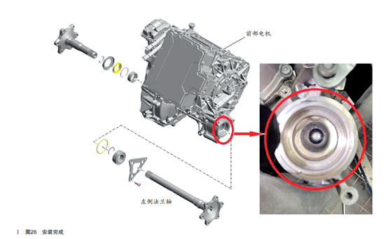
Figure 24
The following assembly and test work were carried out smoothly, and the maintenance work for replacing the front motor of this car has finally come to an end.
Summary: 3D printing technology has been widely used in automobile manufacturing, automobile modification and other fields. It not only shortens the development time of new designs, but also meets the individual needs of designers and engineers. However, the application of 3D printing technology to the field of automobile maintenance is a challenge for automobile maintenance technicians. Due to the bottleneck encountered in the mechanical assembly process, a 3D printed part was required to complete this repair. Since the main engine factory does not provide it, and it is not sold on the market, 3D printing can make up for the lack of equipment in the maintenance process. Auto maintenance technicians are often accustomed to relying on homogeneous solutions from suppliers, and they can casually assemble and combine machinery. Once the technical documents of the system are missing and the basic skills of mechanical assembly are not solid, they will repeat simple mistakes.
Helo, My auto Audi e-tron 55 quattro 2019 problem motor eléctrico dentro water?