

[Repair Case] 2021 Mercedes-Benz GLA200 instrument prompts "auxiliary battery failure"
Posted by Tony Brown on
Model: 2021 Mercedes-Benz GLA200
Issue: The meter displays a white text prompting "Auxiliary battery failure".
Troubleshooting:
The problem persists, and there is no unusual sensation while driving. Connect the diagnostic instrument to do a brief test and discover that the N73 has set a fault code for the current state: the B21DC01 electronic ignition switch's buffer battery is malfunctioning.
Check the vehicle registration card; this vehicle has CODE429, is equipped with a 700.4 seven-speed dual-clutch automatic gearbox, and the parking pawl lifting solenoid valve L21 is part of the electromechanical parking pawl placed on the dual-clutch transmission's casing (as shown in Figure 1).

Figure 1
The components of the Park pawl lift solenoid valve L21 are as follows:
Double ball joint with socket & Magnet.
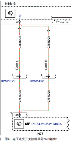
When the parking pawl lift solenoid valve L21 is engaged by the dual clutch transmission control unit N15/13, the emergency-P function is enabled. The parking pawl lift solenoid valve L21 is actuated by the dual clutch transmission control unit N15/13, and the double ball joint with sleeve is pulled away from the magnet. The emergency lock piston and the emergency lock are then used to activate the emergency parking function.
If the voltage of the on-board electrical system is interrupted, such as after a vehicle collision accident, the electronic ignition switch control unit N73 will perform the actuation, and the G1/7 additional battery will provide backup power to N73 through the additional battery fuse F25/1 (10A, red) 30b , N73 actuates the parking pawl lift solenoid valve L21 through the emergency path to the dual clutch transmission control unit N15/13 pin 17 (P-NOT parking pawl) to engage the transmission gear P under low voltage conditions , to prevent slipping.
The relevant circuit diagrams are shown in Figure 2 and Figure 3.
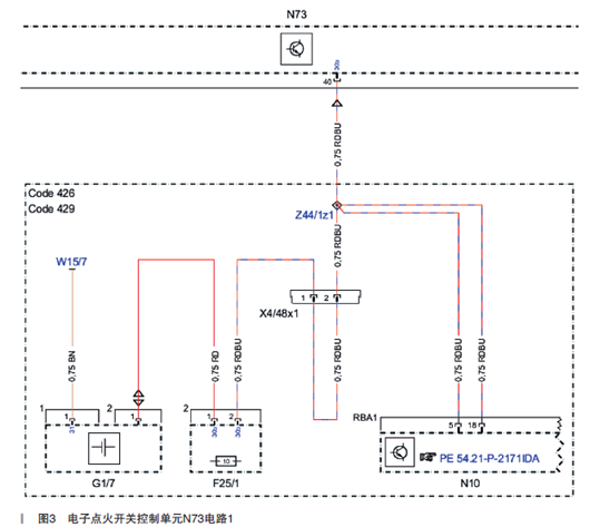
Figure 3
One of the functions of the signal acquisition and actuation control unit N10 is the energy management of the vehicle. The N10 processes the signal from the battery sensor B95 and evaluates the state of charge of the on-board grid battery G1; and directly monitors the additional battery G1/7 via pins 5 and 18 The voltage and current can be charged to the additional battery G1/7 through pin 18 in a timely manner.
Additional battery G1/7 and additional battery fuse F25/1 are installed under the saddle, as shown in Figure 4.

According to the working principle of the system and the analysis of fault codes, the possible causes of the auxiliary battery failure displayed by the instrument are as follows:
Ignition switch N73 software failure
Additional battery G1/7 faulty
G1/7 related line faults, such as poor grounding, short circuit of power line to ground, etc.
Attempt to upgrade the ignition switch N73 software, but no new software was found; check the actual value of N73, the voltage of the 12V on-board power grid battery G1 is 12.6V, but the voltage of the additional battery G1/7 is 0V, which is abnormal; check the additional battery G1 The plug of /7 is not loose; the resistance between the negative wire and the body is 0.2Ω, which is normal; check that the grounding point W15/7 of the additional battery G1/7 located on the right side of the passenger footwell (as shown in Figure 5) has no corrosion, ablation or loosening abnormal conditions.

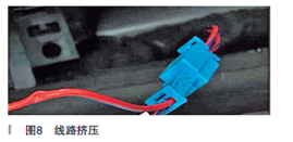
Measure the voltage of the additional battery G1/7 and it is 12.9V, which is normal; check that the fuse F25/1 of the additional battery is blown; measure the resistance between the 2 feet of the fuse F25/1 and the body to be 0.2Ω, indicating that the line has a short circuit to ground; Inspection found that under the right front door sill trim, near the connector X4/48x1 (as shown in Figure 6), the power cable (red and blue) from the additional battery G1/7 to the ignition switch N73 was squeezed by the trim fixing iron card (as shown in Figure 7), resulting in a short circuit to ground and fuse F25/10 blown.
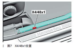
Figure 6
Figure 7
Troubleshooting: Replace the fuse F25/1 (10A), repair the wiring harness, reassemble, the fault disappears.
Fault summary: Because this car is not installed, the analysis is caused by assembly errors on the production line.