

[Repair Case] 2018 Mercedes-Benz E300 instrument prompts "Blind Spot Assist System Stops Working"
Posted by Tony Brown on
Model: Mercedes-Benz E300, equipped with 274.920 engine.
Driving mileage: 12,415 miles
Fault phenomenon: The instrument prompts “Blind Spot Assist Has Stopped Working”.
Troubleshooting:
Connect the XENTRY diagnostic instrument and conduct a quick test. The integrated radar sensor in the left rear bumper of the B92/11 has set a fault code: C110100 radar sensor 1 has a functional failure, A+S.
Check the car’s registration card to confirm that the car is equipped with a blind spot assist system (code 234). The blind spot assist system uses short-range radar to monitor the rear and side areas of the vehicle, and if necessary, informs the driver through visual and audible warnings that it is not recommended to Active lane change (turn signal activated) during this time. Broadly speaking, Blind Spot Assist acts as an extended mirror. The visual warning is issued through the Blind Spot Assist system warning indicators on the exterior mirrors on both sides, and the audible warning is output through the instrument speakers, as shown in Figure 1.
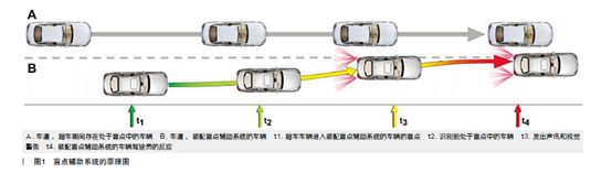
Figure 1
The working conditions of the system are the vehicle is moving forward; there is no low-voltage or over-voltage; the vehicle speed is greater than or equal to 10km/h; the engine is running or the transmission system is working normally.
Areas that cannot be seen through the exterior and interior mirrors are monitored by the integrated radar sensor in the outer right rear bumper and the integrated radar sensor in the outer left rear bumper, all relevant data are evaluated by the integrated radar sensor in the rear bumper. The right rear bumper radar sensor requests warning output accordingly.
The specific function sequence is as follows:
(1) When circuit 15 is turned on, the Blind Spot Assist system warning indicator light on the outside rear-view mirror lights up in red until the engine runs.
(2) If a vehicle is within the detection range of the radar sensor system when the vehicle speed is greater than or equal to 12km/h, the Blind Spot Assist system warning indicator in the exterior rear-view mirror will light up in red to warn the driver, indicating that the vehicle is in the In the blind spot on this side, the overtaking advance warning is issued before the vehicle enters the blind spot and is part of the system limitation.
(3) If the driver attempts to change lanes despite the blind spot assist system warning indicator being illuminated, and this is indicated by operating the combination switch (turn signal enable), when the target vehicle is about to approach the system vehicle, additionally through the instrument speaker. A double warning tone sounds and the Blind Spot Assist warning indicator flashes.
(4) If the vehicle leaves the detection range of the radar sensor system, the Blind Spot Assist system warning light, which is flashing red, goes out.
The radar sensor integrated in the rear bumper works according to the “master-slave” principle, the master or slave function can be determined by the connector coding. The B92/6 integrated radar sensor in the right rear bumper performs the main function, which means that the B92/11 integrated radar sensor in the left rear bumper transmits its information via the peripheral controller area network (CAN) to the right rear bumper integrated The radar sensor, which evaluates the corresponding information from the two rear bumper-integrated radar sensors and transmits the corresponding request or data to the corresponding control unit via the peripheral controller area network (CAN), as shown in Figure 2 .
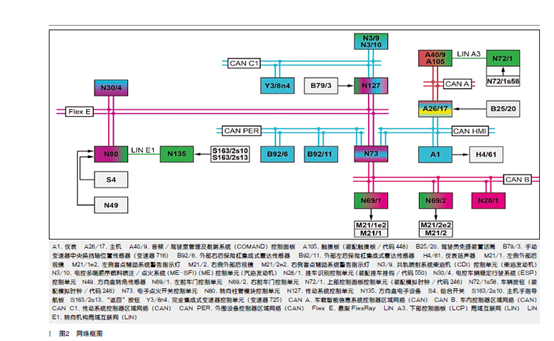
Figure 2
Objects (vehicles in blind spots) are detected using a radar measurement procedure, the radar sensor integrated in the rear bumper emits a beam of electromagnetic waves called “primary signals”, which, if they encounter an object, are reflected by it and act as secondary signals, which are received again by the corresponding radar sensors integrated in the rear bumper. These signals can be used to calculate the distance and movement speed of the detected objects from the vehicle and their angle relative to the vehicle. The detection range of the radar sensor integrated in the rear bumper determined by the angle of the radar wave.
The circuit diagram of the rear bumper integrated radar sensors B29/11 and B29/6 is shown in Figure 3.

Figure 3
According to the working principle of the system, circuit diagram and fault code analysis, the possible fault causes are:
B92/11 The left rear bumper integrated radar sensor is not securely installed
B92/11 Left rear bumper integrated radar sensor mounting bracket is not secure on bumper
B92/11 Dirt or foreign object between the integrated radar sensor in the left rear bumper and the bumper
B92/11 The left rear bumper integrated radar sensor is not installed in the correct position or is not installed correctly
B92/11 Damage to the bumper surface corresponding to the integrated radar sensor in the left rear bumper
B92/11 Left rear bumper integrated radar sensor The corresponding bumper surface is overpainted and mud scraped
B92/11 Left rear bumper integrated radar sensor wiring fault, such as corroded or loose connector
B92/11 Left rear bumper integrated radar sensor software failure
B92/11 Left rear bumper integrated radar sensor electrical failure
The steps to check are as follows:
Check that the integrated radar sensor in the left rear bumper of B92/11 is securely installed, OK
Check that the B92/11 left rear bumper integrated radar sensor mounting bracket is firmly on the bumper, OK
Check B92/11 there is no dirt or foreign matter between the integrated radar sensor in the left rear bumper and the bumper, OK
Check that the B92/11 left rear bumper integrated radar sensor is installed in the correct position and installed correctly, OK
Check B92/11 left rear bumper integrated radar sensor corresponding bumper surface without damage, OK
Check the B92/11 left rear bumper integrated radar sensor that the corresponding bumper surface has not been painted and scraped, OK
Check B92/11 left rear bumper integrated radar sensor actual value power supply voltage 11.5V (11.0~15.5V), OK
Check the B92/11 integrated radar sensor circuit in the left rear bumper, there is no abnormality, and there is no corrosion or loose plug, OK
Tried to upgrade B92/11 left rear bumper integrated radar sensor software and SCN coding, the fault remains the same
Check that the appearance of the integrated radar sensor in the left rear bumper of B92/11 has no obvious deformation and other signs of collision and external force, OK
Attempt to swap the B92/11 left rear bumper integrated radar sensor with the B92/6 right rear bumper integrated radar sensor, the result failed, the B92/6 right rear bumper integrated radar sensor set a fault code C110178. Radar sensor 1 has a functional failure.
According to comprehensive analysis, the cause of the failure is the internal electrical failure of the radar sensor integrated in the left rear bumper of the B92/11.
Fault summary: B92/11 left rear bumper integrated radar sensor has the same part number as B92/6 right rear bumper integrated radar sensor and can be interchanged; the two rear bumper integrated radar sensors work based on “master-slave” principle, the system distinguishes the left and right radar sensors by whether the 5th and 6th feet are grounded.
thanks, so I can check if it s electicity issue with check 11,5V.
I given to mercedes but they failed found out.