

[Repair Case] Mercedes-Benz C300 steering wheel vibration
Posted by Tony Brown on
Model: C300 with 274 engine.
Driving Mileage: 18,465 miles
Issue: When the ignition switch is turned on, the steering wheel vibrates, and the multi-function display in the center of the instrument prompts "the lane keeping assist system has stopped working".
Troubleshooting: Connect the diagnostic instrument to perform a quick test. The steering column module N80 has a fault code: B1E9F15 steering wheel electronic device has functional failure, there is a short circuit or open circuit to the positive pole; B1EB015 lane keeping assist system has a fault, there is short circuit or open circuit to positive; there is also a fault code B1E9F19 in the stored state, the steering wheel electronics is functionally faulty and the current limit is exceeded.
Check the registration card, this car is equipped with lane keeping assist system (CODE 476), as shown in Figure 1 and Figure 2. The main control module of this system is the A40/11 plane detection multi-function camera. The function of this system is to detect whether there is the phenomenon of driving over the lane markings unintentionally. The system detects the multi-function camera A40 through the plane located in front of the rearview mirror. The A40/11 optically records and recognizes the behavior of crossing lane markings, and after comprehensive consideration of the driver's actions, under certain conditions, a haptic warning is issued to the driver by triggering a vibration motor on the steering wheel, which generates a haptic warning.
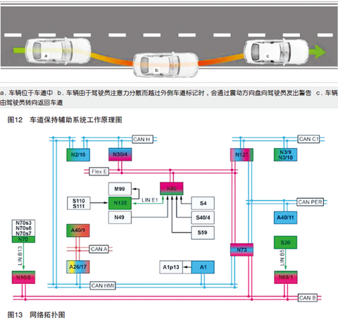
Figure 1
Figure 2
The owner can select the following operating modes in the auxiliary menu in the instrument cluster: ① Standard, increased sensitivity (warning earlier and more frequently); ② Moderate, decreased sensitivity (warning later and less frequently).
The system will not warn or suppress the warning if the following driver actions are detected: ① Significantly active steering (steering intervention) (identified by the steering wheel angle sensor inside the steering column module N80); ② Braking (stabilized by the electronically controlled vehicle) The driving system ESP control unit N30/4 provides information on the state of the brake pedal), acceleration (information about the position of the accelerator pedal is transmitted by the engine control unit N3/10) or approach angle (the vehicle active approach angle); ③ turn signal (the switch position of the combination switch is directly read by the steering column tube module N80); ④ sporty driving (high-speed cornering or severe acceleration) (by the acceleration integrated in the auxiliary protection system control unit N2/10) sensor to detect acceleration/yaw rate).
Lane Keeping Assist Master Control Module A40/11 (Plane Detection Multi-Function Camera) also monitors controls or switches located in the vicinity of the driver and which interfere with the driver's attention when operated and, if a control intervention is detected, Lane Keeping Assist will perceive the driver as distracted, the Lane Keep Assist system will warn more quickly and more frequently, and the vehicle will immediately output active warnings when the vehicle is near or across lane markings.
The specific conditions for the system to issue a warning include: (1) the lane recognition of the plane detection multi-function camera; (2) the vehicle speed is 37-124 mph (3) the radius of the curve is greater than 492ft; (4) the lane departure is recognized.
The working sequence for the system to issue a warning is as follows: The flat detection multifunction camera A40/11 transmits the request to actuate the steering wheel vibration motor to the steering column module control unit via the peripheral controller area network (CAN), the electronic ignition switch control unit and the chassis FlexRay N80, the steering column module control unit transmits the request via the steering mechanism local internet (LIN) to the steering wheel electronics N135, which then activates the steering wheel vibration motor M99, which is continuously activated for 1.5s with the intensity of the haptic warning matched to vehicle speed to avoid perceptible effects from the suspension at high speeds.
The steering wheel module N135 is located directly behind the multi-function steering wheel (MFL) (as shown in Figure 3 and Figure 4), on the steering column tube of the steering column. Read the signals from the following components through the straight-through line: ①R22/4 steering wheel heater; ②S110 left multi-function steering wheel button group; ③S111 right multi-function steering wheel button group; ④S111/1 steering wheel high shift button; Resist button; ⑥4 horn buttons N135s1, N135s2, N135s3, N135s4; ⑦M99 steering wheel vibration motor.
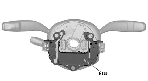
Figure 3
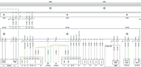
Figure 4
According to the fault code and fault cause analysis, the possible fault causes are:
(1) The steering wheel electronic device N135 is short-circuited or open-circuited to the positive pole.
(2) The M99 wire of the steering wheel vibration motor is short-circuited to the positive electrode.
(3) Internal electrical failure of steering wheel electronic device N135.
The inspection found that the N135 plug of the steering wheel electronic device was not loose, and the power supply and grounding voltage were normal; the wires of the component N135 were not broken or worn; dismantling and inspecting the N135 found that the electronic components inside the steering wheel electronic device had been ablated.
After debugging with the same car, the function returned to normal.
To sum up, the ablation of the internal components of the component N135 causes the steering wheel vibration motor M99 to work as soon as the ignition switch is turned on.
Troubleshooting: Replace steering wheel electronics N135.
Fault summary: The steering wheel electronic device N135 communicates with the steering column tube module N80 through the steering mechanism Local Area Internet (LIN), and directly drives the steering wheel vibration motor M99. This is an important link and content of the working principle of the lane keeping assist system.