

[Repair Case] 2022 Land Rover Range Rover after turning on the air conditioner, it automatically turns off.
Posted by Tony Brown on
Car: Land Rover
Model: Range Rover
System: Air Conditioning
Year model: 2022
Fault phenomenon: The customer complained about operating the lower display screen of the integrated control panel after starting the vehicle, and found that after the vehicle air conditioner was turned on, it automatically turned off. After the test vehicle seat heating and cooling functions were turned on, it still automatically turned off.
The driver found this fault, which has nothing to do with the ambient temperature and is permanent. Check that the vehicle has no additional or modified items, and the maintenance history query has no relevant maintenance records. Check that the surface of the integrated control panel of the vehicle is not damaged and is properly installed, and other functions of the operation control panel turn on and off normally, and there is no automatic shutdown phenomenon, and the fault caused by the display screen under the integrated panel is excluded.
According to the fault phenomenon, connect the diagnostic instrument to read the vehicle-related fault codes, and there is no relevant fault code.
Diagnosis:
Vehicle modifications or environmental electronic interference
Integrated display ICDM module under the vehicle, software failure
Vehicle profile failure
Air conditioning control module HVAC software or hardware failure
Air conditioning control system sensor or actuator LIN signal or fault
Air conditioning control module HVAC module control CAN signal failure
Move the vehicle to test the fault, and check that the vehicle has no additional or modified items.
Read the vehicle air conditioning control module HVAC, and check that the module software version is up to date. Run the vehicle air conditioning control module HVAC module self-check operation as needed, and if there is no fault code in the self-check, run the HVAC module function of the vehicle air conditioning control module and reset the ambient temperature algorithm. Even though the vehicle reset operation is successful, the fault still exists. Run the vehicle CCF configuration file to test that the vehicle fault remains the same, and so does powering off the negative cable of the vehicle battery for about 15 minutes.
Read the vehicle interactive display module A (IDMA) without relevant fault codes, and the software is the latest version without updated software. After locking the vehicle to sleep overnight, the fault remains still.
Observe the vehicle. After the air conditioning system is turned off automatically, it is found that there is air blowing from the feet of the vehicle and the air outlet of the glass. The air volume is relatively small and it feels like natural wind. Observing the engine compartment, it is found that after the vehicle is started and after a delay of a few seconds, the electromagnetic clutch of the air conditioner compressor pulls in the compressor and operates, and the air conditioner panel shows that the air conditioner is turned off.
Read the air-conditioning compressor flow control valve, the current of the control valve is 0.442A and the air-conditioning compressor is controlled to work. After starting the vehicle, it is read that the low-pressure pressure of the air-conditioning is 200kPa, the high-pressure pressure is 900kPa, and the air-conditioning system pressure is normal.
After many tests, it is found that the vehicle air conditioner automatically returns to the lowest temperature of 0L after adjusting, and the air volume of the air conditioner could not be adjusted. Then, the air conditioner automatically turned off after a few seconds.
According to the diagnosis and analysis of the above fault causes, it is suspected that there is a short circuit in the output LIN of the air conditioner, and either the sensor and actuator are faulty or the signal is inaccurate.
Use an oscilloscope to measure the output LIN-A, LIN-B, and LIN-E of the air-conditioning control module respectively, and the measured LIN communication signal is normal (as shown in Figure 1).
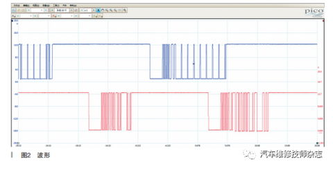
Figure 1
According to the above measurement, the air-conditioning system does not work due to the fault of the LIN signal of the air-conditioning control module. Query the network topology of the air conditioning system, as shown in Figure 2.
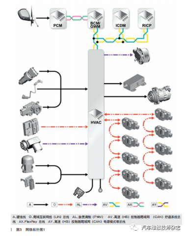
Figure 2
According to the principle analysis of the network topology diagram, the HVAC communication network topology diagram of the vehicle air conditioning control module shows that there is only comfort CAN, and the communication of the HVAC module of the air conditioning control module is normal, the module self-checking on demand has no problem, the module software upgrade is normal, and the diagnosis and maintenance are in a deadlock.
Continue checking the Air Conditioning Control Module (HVAC). The HVAC Control Module processes inputs from the Interactive Control Display Module (ICDM), Rear Integrated Control Panel (RICP), and system sensors, and in response to these inputs, the HVAC outputs control signals to the Air Conditioning (A/C) system and the heating and ventilation system.
There are 4 electrical connectors for connecting HVAC and vehicle wiring. The HVAC communicates with the recirculation, temperature mixing, distribution, and center face vent motors using hardwired inputs from system sensors, and the Local Interconnect Network (LIN) bus. The HVAC also uses the High Speed (HS) Controller Area Network (CAN) Comfort System Bus and the HS CAN Power Mode 0 bus to communicate with other control modules on the vehicle.
According to the above principles, the air-conditioning control module HVAC has two CAN communication networks, the comfort CAN and the power mode 0-CAN control network signal, whether the air-conditioning system failure is the control CAN signal failure that causes the air-conditioning system to be in failure mode. View the circuit diagram, as shown in Figure3.
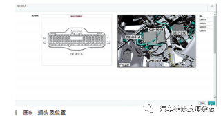
Figure 3
Use an oscilloscope to measure the HVAC comfort CAN signal waveform of the air conditioning control module, and C2H101A-6 and C2H101A-7 measure the abnormal comfort CAN signal waveform, as shown in Figure 4.
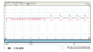
Figure 4
According to the comfort CAN waveform measurement, C2H101A-6 comfort CAN-H has an open circuit.
Unplug the HVAC control plug C2H101A of the air conditioning control module and measure C2H101A-6 and C2H101A-7. It is found that C2H101A-6 has no voltage and waveform output (as shown in Figure 5). Check to confirm that the C2H101A-6 Comfort CAN-H has an open circuit.
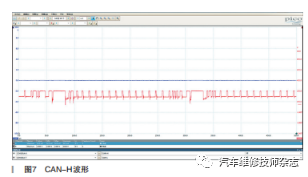
Figure 5
According to the circuit diagram analysis, the Comfort CAN network passes through the head-up display module before reaching the HVAC module. Start the vehicle and check that the head-up display function of the vehicle is normal, indicating that the head-up display comfort CAN network communication is normal. Use a multimeter to measure that C2H101A-6 to C32-A2-10 are open and non-conductive, and the resistance value is infinite. The vehicle HUD is working fine and the analysis breakpoint should be disconnected from the S2DB27T node.
The C2H101A-6 to C32-A2-10 are cross-connected for testing. The vehicle air conditioning system can be adjusted and the function returns to normal. Fault analysis Comfort CAN network interruption Why is the air conditioning control module having communication detection and normal programming?
Refer to the circuit diagram, disconnect the HVAC module, power mode 0-CAN control plug C2H101C-12 and C2H101C-11, connect 2H101A-6 to C32-A2-10 of Comfort CAN C, and use the diagnostic tester to re-read Get the HVAC module information of the air conditioning control module, and find that the module loses communication and the module communication is interrupted.
View the network topology diagram, as shown in Figure 6.
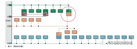
Figure 6
According to the above inspection and analysis, the main communication network of the new Range Rover air conditioner control module is the power mode 0-CAN for communication programming, and the comfortable CAN network signal is used as the control signal network, so the diagnostic instrument cannot diagnose. There is a fault in the HVAC control module HVAC programming and on-demand self-test are normal.
There is an open circuit between the HVAC comfort CANC-H plug 2H101A-6 of the air conditioning control module and the node S2DB27T. View the vehicle wiring harness diagram as shown in Figure 7.
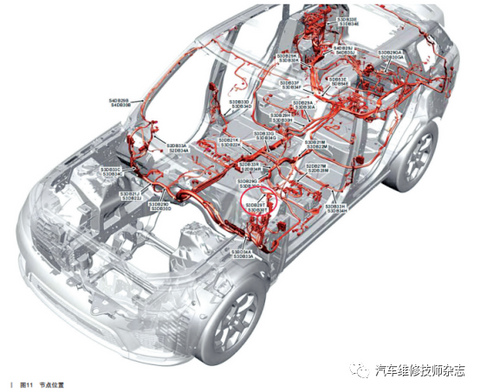
Figure 7
According to the node location diagram, the S2DB27T node is inside the instrument panel. Remove the instrument panel to check and find that the breakpoint is indeed at the S2DB27T node position, and the line is broken, as shown in Figure 8.
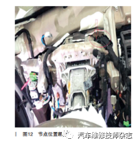
Figure 8
Repair the disconnected wiring harness, use an oscilloscope to measure the HVAC comfort CAN signal waveform of the air conditioning control module, the signals of C2H101A-6 and C2H101A-7 are normal (as shown in Figure 9), and test the vehicle for troubleshooting.
Figure 9
Fault Summary: The HVAC comfort CAN-H network of the air-conditioning control module is disconnected, which causes the HVAC of the air-conditioning control module to fail to receive the CAN network signal control signal sent by the display screen under the integrated control module. This results in the air-conditioning being unable to control the opening and closing.