【Repair Case】2012 BMW 730Li left front door cannot be opened
Posted by Tony Brown on
Model: F02, equipped with N52 engine.
Driving mileage: 7659 miles.
Fault phenomenon: The left front door of BMW 730Li could neither be opened inside or outside, and the other three doors were kept unlocked and could be opened on both sides.
Diagnosis: There is no relevant fault record detected by the diagnostic instrument. When the car is locked with the car key, the four door locks do not respond, only the trunk and fuel tank cover can be locked, and there are double flashing warning signs. When unlocking with the car key, the 4 door locks do not respond, the trunk can be unlocked, and the double flashing also has a flashing indication warning. When the central locking button in the car is operated, the four door locks do not operate, and the trunk can be unlocked and locked normally.
The control logic of the vehicle central lock: after pressing the unlock button or the central lock button of the remote control, the identification sensor sends out an encrypted remote-control signal, and the remote-control receiver receives the remote-control signal through the integrated antenna. Demodulate, edit, and check the signal in the remote-control receiver. That is, there is a constant "value" in the radio signal that belongs to the vehicle, which is detected by the remote-control receiver. Only when this constant value is correct is the information transmitted to the control unit via the LIN bus. That is, the master key of another vehicle (same production line) or the radio signal of the identification sensor does not have any effect on boarding or acting on the vehicle. The confirmation of the remote-control signal will then be performed in the control unit. If there is an authorized request at this time, the control unit wakes up the vehicle and causes the vehicle to be released from the interlock. The transmission frequency of the master key or identification sensor currently uses the following high frequency 315MHz, 434MHz, 868MHz. The door locks are equipped with swivel latches and pawls. The door locks can be mechanically or electrically unlocked and then opened.
If the vehicle is equipped with an automatic soft closing system drive, when closing, simply press the door lightly into the door lock, which activates the drive and closes the door completely. 2 central locking motors (high-speed motors with flanged transmission) are integrated in each door lock. The control unit (JBE or FEM) controls the motor. The door lock mechanism can be placed in and out of the interlocked position by these motors.
Interlocking: The doors can also be opened from inside, and all door locks are interlocked. The outer door handle is mechanically disconnected from the door lock. The inner door handle is mechanically connected to the door lock. When the fuse is locked, the doors cannot be opened either from the inside or from the outside (depending on the special equipment and national equipment), during the "fixing" process, the locking pin in the door lock is mechanically released by a clutch.
Unlocking: The doors can be opened from both inside and outside the car, all door locks are in the unlocked state, and the outside handle and inside handle are mechanically connected to the door lock. A Hall sensor is installed in each door lock as a door contact. Hall sensors can identify whether the rotary latch is open or closed. Using the Hall sensor signals, the control unit (FRM or FEM) analyzes the state of the door contacts. The FRM control unit or the FEM control unit sends this status as a message on the K-CAN2 to the CAS control unit (convenient entry and start-up system). The driver's door lock can be used to mechanically interlock or secure the vehicle and unlock it. In the event of a fault in the vehicle's electrical system (e.g., a fully discharged battery), the driver's door can be controlled via the master key or the integrated key in the identification sensor. In addition to the door contacts, the driver's door lock also contains 2 additional Hall sensors. 2 Hall sensors are electronic door lock contacts. Hall sensors acquire the position of the driver's door lock cylinder (interlocked and secured). Automatic release of interlocks due to random electromagnetic strays (EMV = Electromagnetic Compatibility) or manipulative release of interlocks due to targeted electromagnetic strays can thus be avoided.
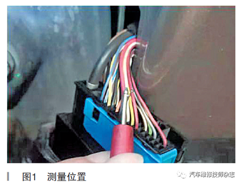
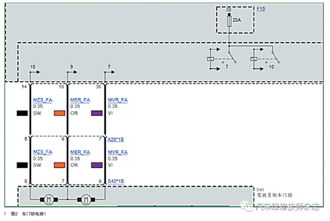
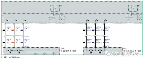
According to the above principal analysis, the following conclusions can be drawn: the vehicle central locking system has been authorized by CAS, because the trunk can be unlocked and locked normally when the key is pressed, and the status of the vehicle door lock is confirmed by double flashing. The fault is locked in the power supply or execution part of the central locking, the part from the JBE to the door lock block. Check that the central control system fuse F14 is normal, and the F15 fuse is normal. According to the ISTA circuit diagram, measure the voltage value of the signal line of the left front door lock and the left rear door lock when the door is unlocked, and there is no voltage on the MER line of the left front door and the left rear door when unlocking. When locked, there is a voltage of 12.01V on the MVR line of the left front door, and there is no voltage output on the MVR line of the left rear door. Continue to check that there is no abnormality in the line from the door to the JBE. Because JBE executes the vehicle lock or unlock request by controlling the interlock relay and unlock relay, it is the internal damage of the JBE that causes the vehicle to fail to control the door lock normally. Generally, the internal relay of the JBE is damaged.
The measurement position and the circuit diagram of the left front door and the left rear door are shown in Figure 1 to Figure 3.

Figure 1

Figure 2

Figure 3
Troubleshooting: Troubleshooting after replacing JBE control unit.
Fault summary: The convenient access and start system (CAS) performs the central control function of the central locking system. After obtaining the legal trigger state of the central locking system from the outside world, it sends out the vehicle unlocking, locking and central insurance locking requests.
The Junction Box Electronics (JBE) performs the unlocking and locking requirements from the CAS to the vehicle.
The Footstep Space Module (FRM) provides the JBE with door status information.
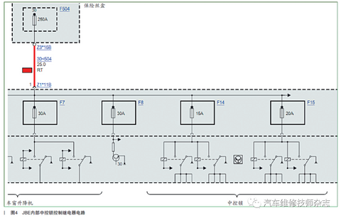
JBE's control of the vehicle door lock motor is realized through the combined work of multiple double-contact relays inside. They combine the circuits that control the forward and reverse rotation of the door lock motor, thereby realizing the functions of unlocking and locking. For example, the power supply of a door lock motor is controlled by a relay, but the grounding is controlled by other relays. According to the requirements of the door status, a relay switches back and forth between power supply and grounding, and some relays control several door locks at the same time. Therefore, damage to a relay or its driving circuit may cause one or more lock blocks to fail to work properly.
The internal central control lock control relay circuit of JBE is shown in Figure 4.

Figure 4
