

[Repair Case] 2011 BMW 535i automatic cruise failure
Posted by Tony Brown on
Model: F07.
Driving Mileage: 37282miles
Issue: The user reports that the cruise system failure warning lamp lights up when the vehicle is driving, and the central information display screen prompts "Automatic cruise system failure! Collision function failure!"
Diagnosis: After picking up the car, it is found that the automatic cruise system fault alarm phenomenon of the vehicle currently exists. Connect ISID for diagnosis and testing, and read the fault content in the vehicle fault memory as follows:
48003B: ICMACC sensor reported failure
482136: ACC sensor is out of adjustment
482130: ACC sensor test run
The new ACC sensor replaces the long-range sensor and two short-range sensors. The ACC sensor and the ACC control unit are one part, which is located behind a detachable grille on the front baffle. As a supplement to the known adaptive constant speed control, the system has Stop and Go functions: 1) Carry out distance control and constant speed control through engine or brake intervention until it enters a standstill state. 2) Automatically start from a standstill after a short parking time (1~3s). 3) Adaptive Brake Assist System.
When setting the speed, it can be selected within the range of 30~180km/h, with 10 as the step value in the comfort mode or 1 as the step value in the fine mode. The set speed is displayed on the instrument cluster (head-up display system can be selected). In addition, you can choose among 4 distances. The ACC sensor is integrated in the ACC control unit. The ACC sensor is a radar sensor that measures the far area (up to 200m) and the near area (up to 60m) in front of the vehicle. The ICM control unit undertakes the following tasks for the adaptive cruise control system with stop-and-go function: 1) Aggregate target data transmitted by radar sensors. 2) Analyze targets and select targets related to distance control. 3) Analyze operating signals and generate display signals. 4) Adjust speed and distance. 5) Actuators that generate standard values and output them to the drive unit and brake via FlexRay. 6) Monitor all input signals, control units (hardware) and vehicle status for faults or unreliable status.
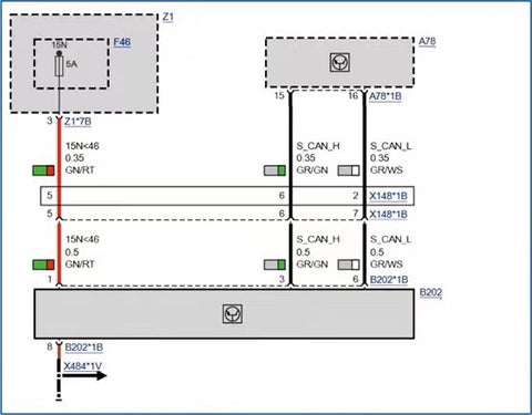
The ACC control unit is connected to the S-CAN (sensor CAN) through the integrated chassis management system (ICM). The sensor CAN works at a transmission speed of 500kbit/s. The sensor CAN has two terminal resistors of 120Ω each. One of them is in the integrated chassis management system (ICM), and the other is integrated in the ACC control unit. The front distributor supplies power to the ACC control unit through the bus terminal KL.15N. The control circuit diagram is shown in the figure.
Select the fault content to execute the detection plan and system analysis. The fault should be due to ACC sensor failure or ACC sensor test run data loss and S-CAN bus failure between ACC sensor and ICM, causing all posture assistance functions based on cruise control to fail. According to the prompts, first test the ACC sensor. All steps are strictly performed in accordance with the requirements. The problem is that the ACC sensor step fails to match after multiple attempts. The vehicle was checked repeatedly, and the matching tool was checked, but no problems were found. It is suspected that the ACC sensor circuit or the ACC sensor is damaged. Check the line speed of the ACC sensor, the power supply of the ACC sensor does not need to be considered, and the module communication is normal. Check and measure the S-CAN bus, because it is suspected that if there is resistance in the bus, or if there is an unobvious failure, whether it will affect the test operation result, the measured bus voltage H is 3V and L is 2V. Measure the connection of the line between the ACC sensor and the ICM. There is no short circuit, open circuit, contact resistance, etc., and confirm that there is no problem on the line. Therefore, the analysis believes that the ACC sensor itself is faulty.
After replacing the ACC sensor, the ACC test run was programmed, and the test run failed.
The front radar sensor needs to be debugged in the following situations:
- 1 calibration fault is stored in the fault code memory
- The front radar sensor was removed and re-installed
- Installed a new front radar sensor
- Guided fault query prompts trial operation
The function of the front radar sensor largely depends on the fine tuning of the sensor. Therefore, debugging must be carried out with extreme caution in the test module according to the instructions, and the following must be paid attention to when successfully debugging:
- The vehicle must not be damaged at the front radar sensor
- The bracket of the front radar sensor must not be deformed
- The front radar sensor must be properly installed in the bracket
- Do not cover the front radar sensor with a license plate
- Be sure to observe the distance between the rearview mirror and the front radar sensor specified in the test module
- The vehicle is at right angles in front of the guide rail
- Check tire inflation pressure and correct if necessary
- Engage the parking brake
- Be careful not to load unevenly on vehicles
- Remove the cap of the rim lock ring
- When installing the quick clamp, pay attention that all the electromagnetic components
must be placed on the wheel bolts correctly
- Rearview mirror must not be damaged
- The rearview mirror must be clean
- Place the rearview mirror on the guide rail correctly with the help of a spirit level and corresponding adjustment bolts
- The rearview mirror must be correctly positioned on the guide rail, aligned by a spirit level
- Pay attention to the tips on adjusting the rearview mirror in the test module
- Do not obstruct the front radar sensor and the rearview mirror during commissioning
- Do not obstruct the rearview mirror during debugging
Visually inspected the bracket of the ACC radar sensor and there was no obvious deformation. The front bumper was further disassembled and checked, and it was found that there was indeed excessive damage in the front of the vehicle. The bumper, bumper lining and other parts were replaced. There is reason to believe that the bracket of the ACC radar sensor There is a possibility of deformation.
Finally, manually adjust the bracket of the ACC radar sensor while measuring until the horizontal and vertical degrees are adjusted to 0. After adjustment, the ACC was tested again, and the result was successful, and the fault was eliminated.